RECTANGULAR NOTCHES
A notch is a device measuring the rate of flow of a liquid through a small channel or tank. It may be defined as an opening in the side of a tank or a small channel in such a way that the liquid are surface in tank or channel is below the edge of opening.
CLASIFICATION OF NOTCHES
Notches are classified as :
- According to the shape of the opening :
- Rectangular notch
- Triangular notch
- Trapezoidal notch
- Stepped notch
- According to the effect of sides on the nappe :
- Notch with end contraction
- Notch without end contraction or suppressed notch
SELECTION OF NOTCHES
The selection of the type of weir to use is based on the range of flows to be measured, the accuracy of measurement needed, and the most economical geometry that fits in given channel. Notches are classified according to the shape of the notch, are notch blade through which the water passes.
The basic types are V-notch, Rectangular, Trapezoidal, End stepped notch. V-notches are good for flows as high as about 13.7 cubic feet per second. Rectangular notches are good for flows as high as about 607 cubic feet per second,
All weirs need to be designed to specific standards for accuracy. Accuracy should be ±5 % of actual flows. The criteria to be met to ensure that accuracy is as close as possible.
RECTANGULAR NOTCHES 
V- NOTCH
TRAPEZOIDAL NOTCH

PROPORTIONS IN SHARP-CRESTED NOTCHES THAT MUST BE MET TO OBTAIN ACCURATE MEASUREMENT.
The following general rules should be observed in the construction and installation of weirs. The sharp-crested weir selected should be one that best fits the circumstances and conditions at the site of measurement. Usually, the rate of flow expected can be roughly estimated in advance and used to select both the type of weir to be used and the dimensions of the weir.
The following criteria should be considered when a specific type of weir is selected for a given application:
• The head of water flowing over the weir should be no less than 0.2 feet and no greater than 2.0 feet for the expected rate of flow.
• Notch length should be selected so that the head for design discharge will be near the maximum. For the rectangular and Cipolletti weirs, the head should not exceed one-third of the length of the weir. That is, if the maximum head is, for example, 1.0 feet, the length of the weir should not be less than 3 feet.
• Set the weir at right angles to the direction of flow in a channel that is straight for a distance upstream from the weir at least ten times the length of the crest of the weir.
• The crest and sides of the weir should be straight and sharp-edged. Each side of the V-notch weir should make a 45° angle with a vertical line through the vertex of the notch. The crest of the rectangular and Cipolletti weirs should be level and the sides should be constructed at exactly the proper angle with the crest.
• Avoid restrictions in the channel below the weir that would cause submergence. The crest must be placed higher than the maximum downstream water surface to allow air to enter below the nappe.
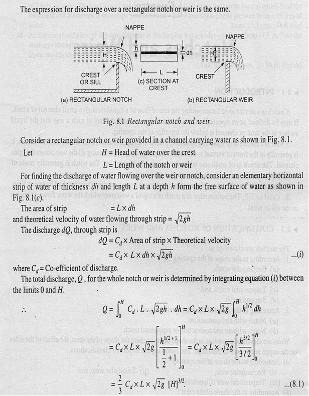
DISCHARGE OVER A RECTANGULAR NOTCH OR WEIR:
CONSTRUCTION DETAILS OF THE RECTANGILAR NOTCH
British standard specification for contracted V-notch and Rectangular notch (British Standard 3680). Are as follows.
The following limitation are placed on V-notch with fully developed contractions.
- 0.05 > h < 0.38m
- P > 0.45m
- h/P < 0.4
- B > 0.9m
- h/B < 0.2
The following limitation are placed on Rectangular notch with fully developed contractions.
- 0.075m > h < 0.6m
- P ≥ 0.3m
- b ≥ 0.3m
- h/b < 0.5
- (B-b) / 2 < 2h

British standard specification and parameters for (a) a V-notch and (b) contracted Rectangular notch (British Standard 3680 : Part 4A : 1965 ).
DESIGN CALCULATIONS COSIDERING BRITISH STANDARD 3680
Let us consider
h = head of water passing over the notch = 0.6m
b = length of crest
B = the width of the approach channel before the notch blade
P=height of the top of the notch blade above the bottom of the notch pool
- 0.075m > h = 0.6m ≤ 0.6m
2) P = > 3h
3h = 3*0.6
= 1.8m
P = 1.5m ≥ 0.3m
3)b = width of notch
= > 2h
2h = 2*0.6
b = 1.2m
4)Ratio of head of water in the notch to the width of notch
h/b < 0.5
h/b = 0.6/1.5
h/b = 0.4 < 0.5
5) (B-b)/2 > 2h
Where, B = width of the plate
2h = 2*0.6
= 1.2m
B = (< 2h) + (< 2h) + (< 2h)
= < 6h
6h = 6*0.6
= 3.6m
B = 3m < 6h
(B-b)/2 = (3-1.5)/2
= 0.75
(B-b)/2 = 0.75 < 2h
MANUFACTURING DETAILS
The model constructed using the ACRYLIC material which is a synthetic fabric and glassy thermoplastic. The dimensions of the rectangular notch are given below and is constructed with the ratio1:10 according to design calculations considering BRITISH STANDARD 3680 : Part 4A : 1965.

Very informative and impressive post you have written, this is quite interesting and i have went through it completely, an upgraded information is shared, keep sharing such valuable information. Theory of Machines 1
ReplyDeleteThank you for giving excellent information. Your website is very great. I am impressed by the details that you have on this site. It reveals how carefully you perceive this subject.
ReplyDeleteClass 11 Physics Syllabus